Virtual Taegis™ NDR Integration Guide🔗
Note
Taegis NDR is an evolution of iSensor, but with a new name and soon with expanded capabilities. You may see some references to the iSensor branding as we complete this transition.
For more information on Taegis™ NDR, see Taegis™ NDR Overview.
Taegis™ NDR is a managed network IDS/IPS solution available from Secureworks. The NDR Device is installed on your network where it monitors all network traffic, leverages our latest threat intelligence to detect network-level threats, and sends detections to Secureworks® Taegis™ XDR when malicious traffic is detected. NDR is a separately contracted feature that may be included with Secureworks® Taegis™ MDR and Secureworks® Taegis™ Elite Threat Hunting.
Supported Features:
- Inline and passive deep packet inspection
- Integration of Counter Threat Unit™ Threat Intelligence
- Ability to block malicious traffic on the network
Data Provided from Integration🔗
| Normalized Data | Out-of-the-Box Detections | Vendor-Specific Detections | |
|---|---|---|---|
| Taegis NDR | Netflow, NIDS | NIDS |
Note
XDR detectors are not guaranteed to be triggered, even if a data source's logs are normalized to a schema associated with a given detector. However, you can create Custom Detection Rules to generate detections based on normalized data from a data source.
Requirements🔗
Review the following requirements prior to implementation.
Deployment Mode🔗
Prior to deploying the virtual NDR Device, an in-depth understanding of your virtual environment is required. You are responsible for configuring your virtual network so the NDR Device may inspect network traffic. Find example configurations in the Virtual NDR Device Deployment Scenarios section.
Connectivity Requirements🔗
| Source | Destination | Port/Protocol |
|---|---|---|
| Taegis™ NDR Device (mgmt IP) | 206.55.100.0/22 216.9.204.0/22 |
TCP/443 (unproxied)* |
* (unproxied) — TCP/443 traffic will need to be excluded from any web content filtering devices. The TCP/443 traffic will be inspected and dropped by most web content filtering devices as malformed HTTPS traffic.
Maximum Transmission Unit (MTU)🔗
Packets that will traverse the virtual NDR Device should have an MTU of 1518 or less. Anything higher will lead to packet loss and have a negative impact on network connectivity.
System Specifications🔗
Secureworks provides a single base image for the virtual NDR Device. Provided below are the default system specifications for the image.
| Item | NDR Device VM Specs |
|---|---|
| CPU | 8 cores |
| Memory | 8 GB |
| Storage | 60 GB |
| Inspection Throughput | 1000 Mbps |
| Sockets | 1 |
| Cores per Socket | 8 |
| Required Features | AVX + AVX2, 1G Hugepages, Virtualization Extensions in CPU Enabled |
Note
The system specifications may need adjustment from the default settings, depending on the amount of inspected network traffic and sensor performance, but must not be set below these minimum values.
NDR Device Deployment Considerations🔗
During the registration of your NDR Device, you must determine the implementation that best serves your organization. To aid in making these decisions, review the following options and determine what will be needed prior to the registration process.
Traffic Processing Mode🔗
-
In inline-active mode (IPS), the recommended installation setup for your NDR Device, all traffic passes through the NDR Device with network traffic being blocked if determined to be malicious by the signature set.
-
In inline-passive mode (IDS), all traffic passes through the NDR Device and is inspected for alerting. The device will only alert to malicious traffic but will not block it. This is also known as inline-sniffing.
-
In sniffer mode (IDS) (non-inline monitor), the network segments to be monitored are spanned to the NDR Device for inspection, but no traffic is blocked.
Important
The virtual NDR Device is dependent on the underlying physical network interface card to provide fail-open support for inline deployments. We strongly recommend using inline mode only when a fail-open card is present.
HOME_NET🔗
HOME_NET is a network or list of networks that are important to you, and that you wish to protect with the NDR Device. The NDR Device uses the defined HOME_NET(s) to determine the traffic that will be inspected. These networks are stored as a variable on the NDR Device called the $HOME_NET. Selecting the correct HOME_NET is extremely important to ensure proper coverage of your network.
EXTERNAL_NET🔗
EXTERNAL_NET is the network you want to protect the HOME_NET from. There are two general options when setting the EXTERNAL_NET on the NDR Device:
!$HOME_NET(i.e., not the networks defined by HOME_NET, which is the traditional configuration)- Any
If there is a large amount of HOME_NET to HOME_NET traffic being seen by the NDR Device, the EXTERNAL_NET should be set to !$HOME_NET to reduce false positives.
Setting the EXTERNAL_NET to !$HOME_NET does not limit the visibility of lateral movement. Our Counter Threat Unit™ (CTU) team writes all of our signatures with directionality in mind. Signatures that are written for vulnerabilities that can be used for lateral movement are written to look for 'any' to 'HOME_NET' traffic.
Proxy Servers🔗
Proxy servers must be accounted for during the NDR Device deployment. Secureworks must know if you have any proxy servers in the monitored environment, if they are transparent or active (clients are forced through the proxy via browser configuration) proxies, what port number the client browsers connect to the proxy on if active, and the IP address of the proxy/proxies.
HTTP_PORTS🔗
After you have defined your proxy server(s), if any are active, we will need to record the port number used by clients when proxying through the active proxy. This port will be used in the $HTTP_PORTS variable. The HTTP_PORTS variable is used to instruct the NDR Device that HTTP traffic is expected on this port and to apply all HTTP signatures to the traffic. If you do NOT have any proxy servers in your environment, but you have HTTP traffic traversing your network on a port other than the following default ports, please ensure they are recorded so they can be added to the HTTP_PORTS variable for proper HTTP traffic inspection.
The default $HTTP_PORTS variable is as follows:
[80,81,88,311,383,591,593,901,1220,1414,1741,1830,2301,2381,2809,3037,3128,3702,4343,4848,5250,6988,7000,7001,7144,7145,7510,7777,7779,8000,8008,8014,8028,8080,8085,8088,8090,8118,8123,8180,8181,8243,8280,8300,8800,8888,8899,9000,9060,9080, 9090,9091,9443,9999,11371,34443,34444,41080,50002,55555]
Signature Sets🔗
Balanced🔗
The balanced policy offers a mix of increased security coverage while still aiming to provide minimal impact to legitimate traffic. Traffic dropped by the balanced policy includes but is not limited to: current threatscape malware and traffic aimed at exploiting high severity vulnerabilities in both widespread and lesser-used software. Traffic that generates detections, but is not dropped, includes but is not limited to: traffic commonly associated with reconnaissance attempts/the noise of the internet, traffic that triggers lower fidelity signatures, and traffic related to questionable activities such as torrent use.
Security🔗
The security policy provides the highest security coverage feasible, while aiming to limit impact to legitimate enterprise traffic. The security policy leans towards stronger security over connectivity, thus it accepts a higher false positive rate in order to provide increased coverage. Traffic dropped by the security policy includes but is not limited to: malware seen within the current threatscape, traffic aimed at exploiting vulnerabilities in both widespread and lesser-used software for high and medium severity vulnerabilities, traffic commonly associated with reconnaissance attempts/the noise of the internet, generic signatures to prevent common attacks such as SQL injection and Cross-Site Scripting attacks, and traffic related to questionable activities such as torrent use.
Connectivity🔗
The connectivity policy protects against the most severe threats, which have the highest risk within an enterprise environment. It provides minimal impact to legitimate traffic. Traffic dropped by the connectivity policy includes but is not limited to: current threatscape malware and high threat exploit attempts against known vulnerabilities in widespread software or software actively being exploited in the wild. Traffic that generates detections, but is not dropped, includes but is not limited to: threats identified by signatures that protect against a variety of medium threat events in lesser-used applications. Signatures that generate more noise are disabled by default.
Virtual NDR Device Deployment Scenarios🔗
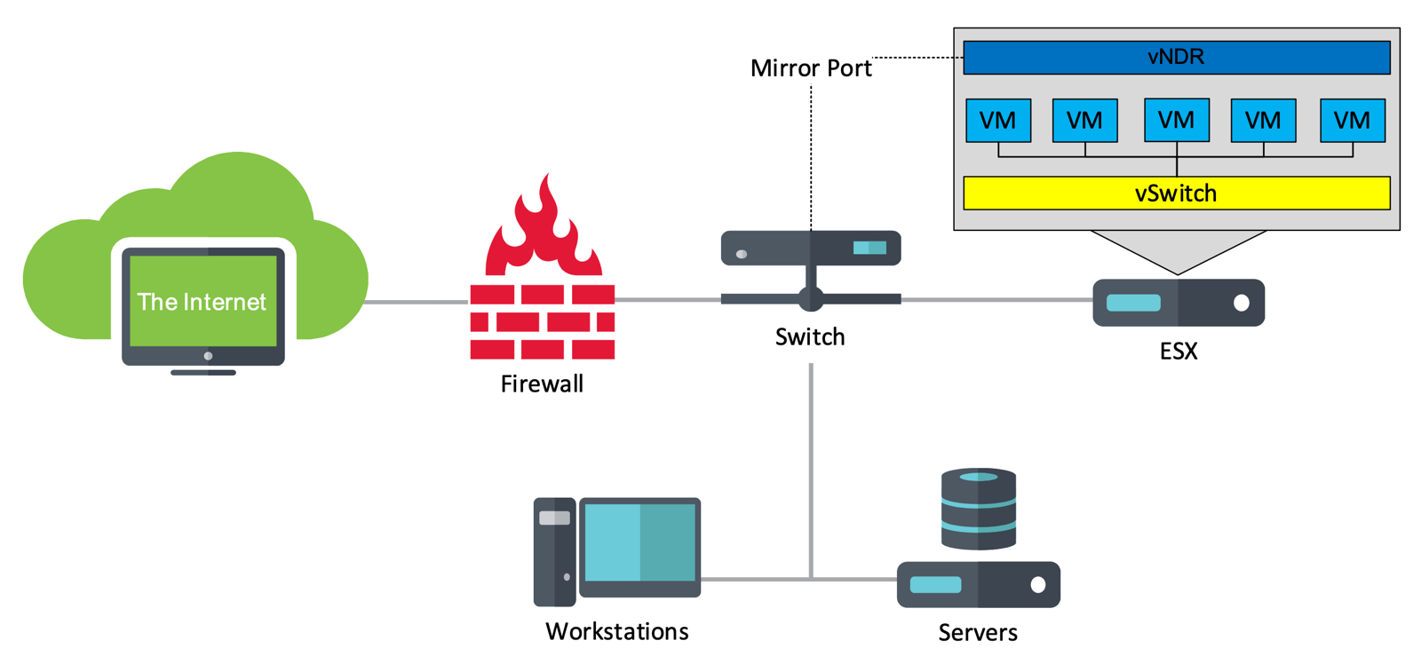
Sniffer — Internal Network Traffic🔗
This deployment example mimics a physical IDS sniffer deployment.
The virtual NDR Device contains at least two virtual interfaces:
- Management traffic
- Network monitoring traffic
- A mirror port is configured on a core switch, which is then directly connected to a physical VMware interface. A virtual switch is created for the mirror port, with promiscuous traffic enabled. The virtual NDR Device has a network monitoring interface configured to use the virtual switch containing the mirror port traffic.
Note
An unused interface on the physical VMware chassis is required for this deployment example.
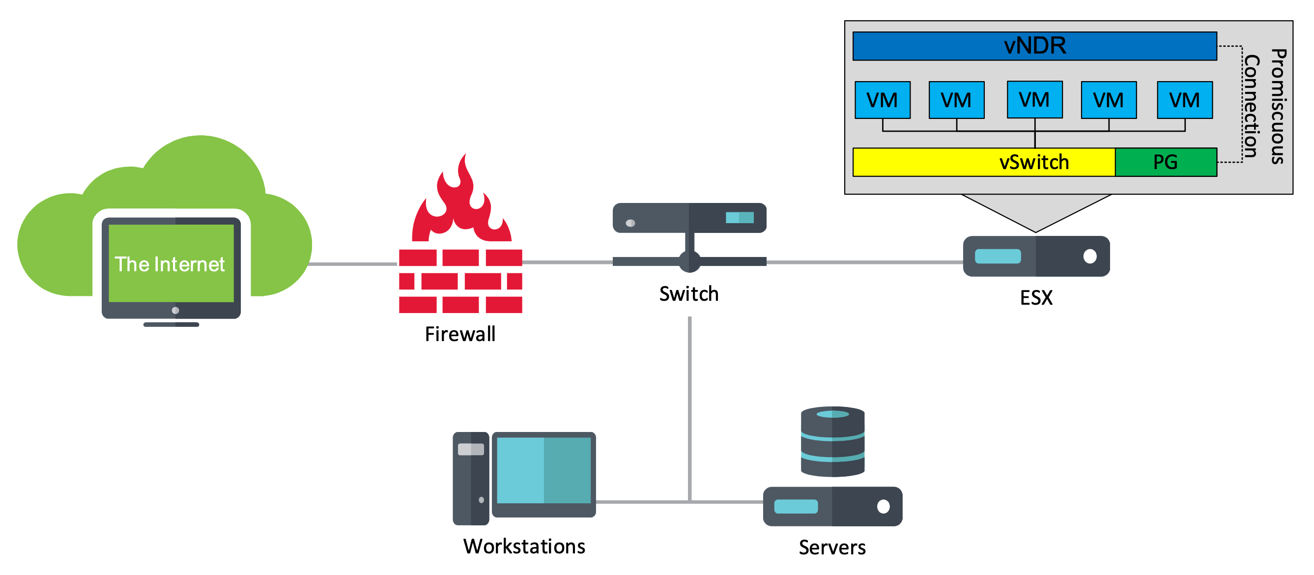
Sniffer — Virtual Traffic Only🔗
This deployment example provides a passive method for the virtual NDR Device to inspect the virtual hosts residing within the ESXi server.
The virtual iSensor contains at least two virtual interfaces:
- Management traffic
- Network monitoring traffic
- Connected to a Port Group (with promiscuous mode enabled) that is part of the virtual switch the monitored virtual machines use for network communication.
- Depending on the amount of virtual switches, additional virtual network monitoring interfaces may be required on the virtual NDR Device.
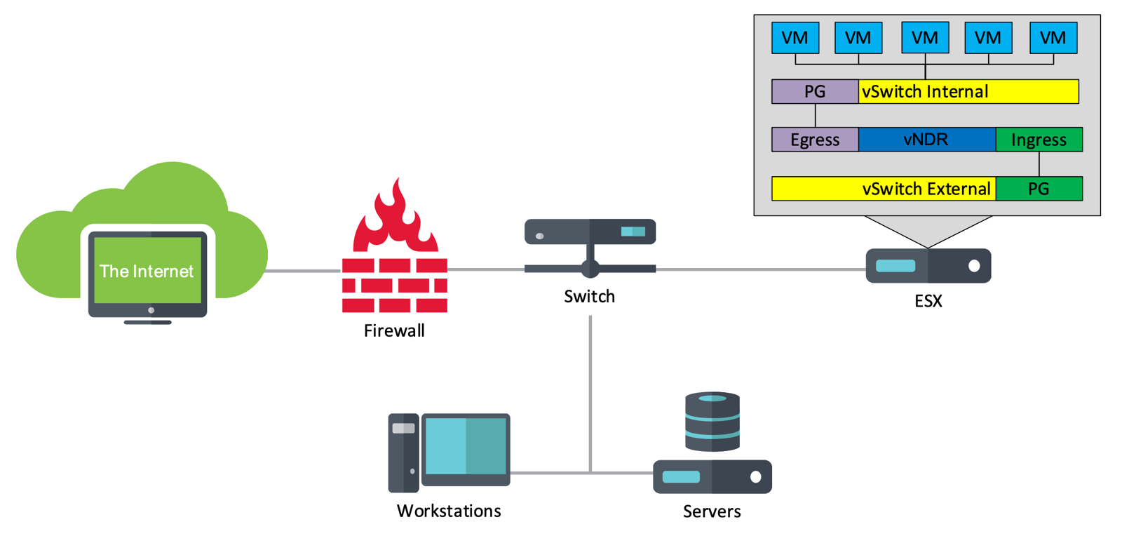
Inline — Virtual Traffic Only, Virtualized Interfaces🔗
Important
This virtual NDR Device deployment will not fail-open; if the NDR Device is restarted or is offline, network traffic will be interrupted.
This deployment example provides an inline method for the virtual NDR Device to inspect the virtual hosts residing within the ESXi server. The virtual NDR Device contains at least three virtual interfaces:
- Management traffic
- Network monitoring traffic
- Two interfaces make up a ‘bridge’: one interface for ingress traffic and one interface for egress traffic. Each Port Group used for inline monitoring must have promiscuous mode enabled.
- In the example below, the ingress interface is bound to Virtual Switch 2 / Port Group Internal.
- In the example below, the egress interface is bound to Virtual Switch 1 / Port Group External.
- Depending on the amount of virtual switches, additional virtual network monitoring interfaces may be required on the virtual NDR Device.
- Two interfaces make up a ‘bridge’: one interface for ingress traffic and one interface for egress traffic. Each Port Group used for inline monitoring must have promiscuous mode enabled.
Download Virtual NDR Device🔗
Follow these steps to download the virtual NDR Device image from Secureworks® Taegis™ XDR.
-
Log in to XDR and select Taegis™ NDR from the Taegis Menu.
-
Select the virtual NDR Device you wish to deploy. The NDR Device details display.
-
From the Registration tab, select the Actions menu and choose Downloads. The Downloads modal displays.
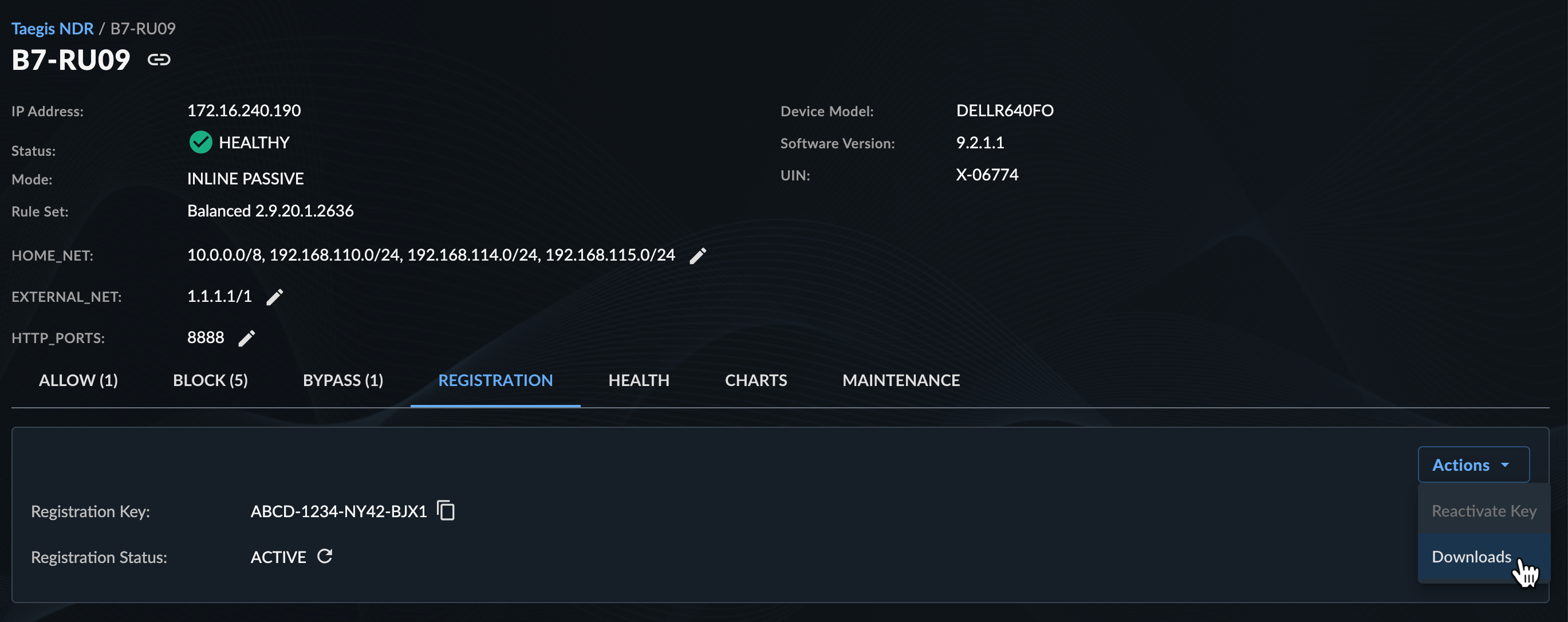
NDR Device Registration Actions -
Make a note of the provided Registration Code to use during device registration, select the checkbox to acknowledge you have read and agree to the information presented, and then select Download.
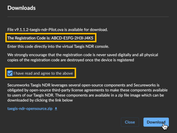
NDR Device Downloads -
Once the download completes proceed to the next section.
Deploy Virtual NDR Device Image🔗
The following deployment example uses an ESXi server. The virtual NDR Device will be deployed in Sniffer mode with one passive monitoring interface.
-
Select Virtual Machines from the Navigator and then choose Create / Register VM.
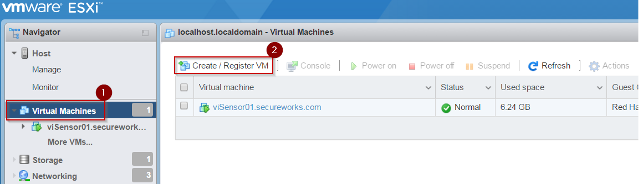
Create VM -
Select Deploy a virtual machine from an OVF or OVA file and select Next.
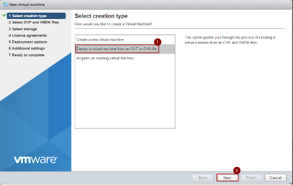
Deploy VM from OVF or OVA File -
Enter a name for the virtual machine, add the virtual NDR Device's OVF and VMDK files, then select Next.
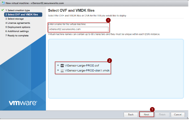
Select files -
Select the appropriate storage location for the virtual NDR Device, then select Next.
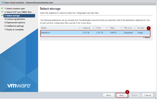
Select Storage -
Define the virtual NDR Device's network mappings:
- Select the appropriate Management Network. In the example below, VM Network is the management network.
- Select the appropriate Network Monitoring networks. In the example below, Network_Monitor is reserved for network monitoring.
- Select Thin or Thick provisioning. Secureworks recommends Thin provisioning.
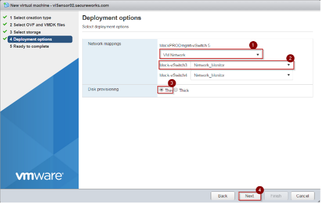
Select Deployment Options -
Select Next after the deployment options are complete. A summary displays.
-
Review the summary and select Finish once you have confirmed everything is correct.
-
ESXi then starts the Virtual Machine creation process, which involves uploading the OVF and VMDK files and may take some time to complete.
Registration Preparation🔗
Before you begin the installation of your NDR Device, prepare the following important pieces of information that you will be prompted for during the installation process:
- Device hostname
- NDR Device Registration Key — Obtained during the Download Virtual NDR Device steps.
- NDR Device mode that you wish to use — At this time, you should have already worked with a Secureworks representative to identify the best solution for you. You must select one of the three modes during the installation process. See Traffic Processing Mode for more information.
- IP address to assign to your NDR Device — If you plan to use a static IP for your NDR Device, please have your IP address, network mask, and gateway address ready for entry during the installation process. These values should have been provisioned by your network team for use by the NDR Device.
Configuration and Registration🔗
Follow these steps to begin installation of your NDR Device:
- Power on the Taegis™ NDR virtual machine.
- Navigate to the virtual NDR Device Console. The NDR Device Configuration Wizard displays.
-
At the initial screen, the NDR Device automatically attempts to detect if the management port is connected. If No interface detected is shown, verify the management interface cable is connected and fully seated. Once done, select Yes to retry the interface detection.
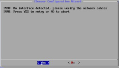
No Interface Detected -
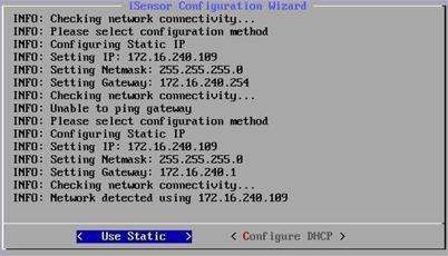
On the next prompt, select Configure Static and then enter your IP, netmask, and gateway information.
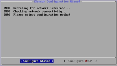
Configure Static IP -
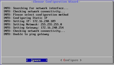
The NDR Device attempts to ping its gateway to verify the information is valid. If a ping failure is expected, select Ignore to continue with the registration process.
Ignore Ping Failure -
Confirm the network configuration by selecting the Use option.
Confirm Configuration -
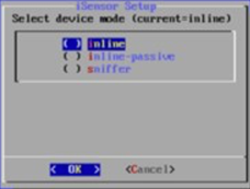
After you confirm the network configuration, select the NDR Device mode desired for your device and then select OK to continue.
Select NDR Device Mode -
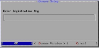
Enter the Registration Key obtained during the Download Virtual NDR Device steps.
Enter Registration Key -
The NDR Device now contacts Secureworks with its Registration Key and completes a fairly lengthy set of steps to download software and configure itself.
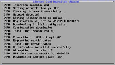
Download and Configuration -
You have now successfully registered and configured your virtual NDR Device. Contact your Secureworks representative to validate connectivity.
Network Reconfiguration🔗
Use the NDR Device CLI to modify the network configuration when needed. Follow these steps:
-
From the console of a physical NDR Device, connect a monitor and keyboard to the system. For virtual devices, navigate to the virtual NDR Device Console. If there is no output present, select Enter to wake the console.
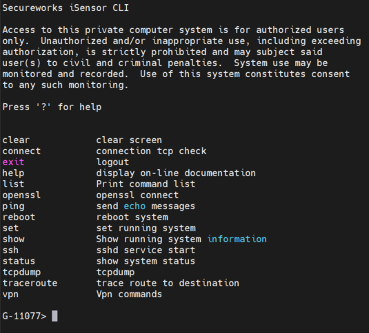
NDR Device CLI -
Use the
setcommand with the following options to make changes to your network configuration:-
set dhcp [enable|disable] -
set gateway <ip> -
set ip <ipv4> <netmask> <gateway> -
set netmode [passive|ips|monitor]
Important
This command should only be used while working with Secureworks support to change the network configuration of the NDR Device. Changes made locally have direct impact on the monitoring and management of the NDR Device and could lead to a service outage if not directed by a member of Secureworks support.
-
Hyper-V Deployment Guidance🔗
You can deploy the virtual NDR Device on Microsoft Hyper-V as well as VMware. For Hyper-V deployments, configure three external virtual switches to provide the management and traffic inspection network connectivity the device requires. The step-by-step instructions below guide you through setting up three external virtual switches in the Hyper-V Manager.
Configure Hyper-V Virtual Switches🔗
Follow these steps to create the required external virtual switches in Hyper-V:
-
Open Hyper-V Manager on your host system.
-
In the Actions pane, select Virtual Switch Manager.
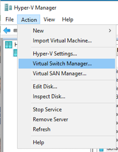
Virtual Switch Manager -
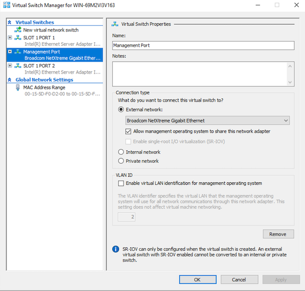
For each of these network interfaces, create a new external virtual switch using the following steps:
Virtual Switch Description Management Handles device management and registration. Capture 1 Serves as the first network monitoring (capture) interface. Capture 2 Serves as the second network monitoring (capture) interface (for inline deployments, this is typically the egress interface). - Select New virtual network switch > External > Create Virtual Switch.
- Enter a descriptive name (such as "NDR Management", "NDR Capture 1", "NDR Capture 2").
- Select the correct physical network adapter for the switch.
- Check Allow management operating system to share this network adapter only for the Management switch.
- Press OK to create the switch.
-
When you create the NDR Device virtual machine, assign its three network adapters to the corresponding virtual switches:
- Adapter 1: Management
- Adapter 2: Capture 1
- Adapter 3: Capture 2
Virtual Switch Manager This setup ensures the NDR Device can communicate for management purposes and monitor or bridge network traffic as your deployment scenario requires.
Note
Hyper-V does not allow for inline deployments. Capture 1 and Capture 2 for Hyper-V allow for two sources of sniffer input.
Tip
For more details on creating and managing virtual switches, refer to Microsoft Hyper-V documentation: Create a Virtual Switch for Hyper-V Virtual Machines.
Use the Deployment PowerShell Script🔗
Deploy the NDR Device on Hyper-V using the provided PowerShell script. Follow these steps:
-
Unzip the deployment package you downloaded from the Taegis UI (for example:
taegis-ndr-prod-9.2.2.1.zip).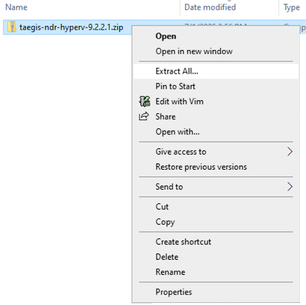
Virtual Switch Manager -
Open PowerShell as Administrator on your Hyper-V host.
-
Change to the directory where you extracted the deployment files:
-
Run the setup script:
-
Respond to the script prompts by providing the switch names and network assignments you defined in the steps above:
- Assign the three external virtual switches:
- Management: for device management and registration.
- Capture 1: for the first network monitoring (capture) interface.
- Capture 2: for the second network monitoring (capture) interface (typically the egress interface for inline deployments).
Enter the same switch names you used when creating the switches (for example:
NDR Management,NDR Capture 1,NDR Capture 2). - Assign the three external virtual switches:
-
After the script completes, you can start and provision your NDR Device on Hyper-V. See Configuration and Registration above.
Registration Error Codes🔗
The following error codes may be seen during configuration/registration. Review the description for details.
| Error Code | Description |
|---|---|
| 20 | User cancelled the process of setting the network configuration |
| 21 | User cancelled the process of selecting the NDR Device mode |
| 22 | User cancelled the process of setting up a registration key |
| 23 | The policy obtained is not a valid XML file |
| 24 | The policy contains an empty VPN password field |
| 25 | VPN connection failed - user decides not to retry |
| 26 | Unable to retrieve RCMS certificates |
| 27 | Certificate tar file missing /var/mqm/ssl/Key.sth file |
| 28 | CIP server information is missing from the policy (Certinit.config) |
| 29 | Unable to obtain UIN - Server provided an invalid response |
| 30 | Unable to obtain UIN - Server provided no response |
| 31 | Imagetools configuration is missing the NDR Device Version |
| 32 | Image MD5Sum didn't match what the server MD5Sum |
| 33 | Image installation failed (instimage.barebone) |
VMware — Virtual Networking Guidance🔗
Secureworks may not assist with the creation or modification of your virtual environment. Please reference VMware documentation, specific to virtual networking, on how to add, remove, or modify virtual networks. Ensure that the vendor documentation matches the version of ESXi or vSphere in your environment.
As an example, the publicly available About vSphere Networking documentation provides a virtual network overview and configuration guidance for versions 7.0 and later. The following are relevant sections of this documentation:
- Reference Create a vSphere Standard Switch for information on how to create a vSphere Standard Switch.
- Reference Port Group Configuration for Virtual Machines for information on how to create a port group.
- Reference Configure the Security Policy for a vSphere Standard Switch or Standard Port Group for information on how to enable Promiscuous mode within a port group.
Virtual Machine FAQ🔗
What version of ESXi is supported?
ESXi v6.5 is EOL. v7.0 and later are preferred and are the official supported versions.
How many cores do I need?
Hardware has minimum 8 cores and 8 GB of memory.
What hardware limits are there?
The underlying CPU must be an x86 CPU and requires AVX instructions support.
What configurations are supported?
| Memory | Cores | Cores per Sockets |
|---|---|---|
| 8Gb | 8 | 8 |
| 16Gb | 8 | 8 |
What cores and sockets do I set for VMware Virtual Machine version of Taegis™ NDR v9?
See System Specifications. The ESXi GUI settings look like the following:
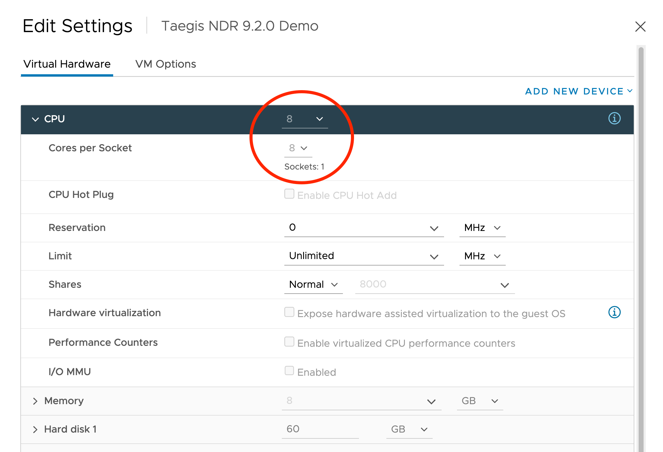
How many sockets does my virtual NDR Device have?
NDR Devices for VMware can only be configured with one CPU socket. To see how many sockets your NDR Device is configured for, do as follows:
- In vSphere, edit the Device Settings.
- Open the CPU under Virtual Hardware.
- Set the number of Cores per Socket to equal the number of CPUs.
- Sockets then show 1.
Taegis™ NDR v9 only supports one socket.