On-Premises HA Data Collector🔗
A Highly Available (HA) Collector is a collector deployed across multiple hosts. HA Collectors are deployed in active-active, multi-master configurations. Because of this multi-node configuration, it eliminates a single point of failure. This means all nodes are up and running and if a node goes down, the other nodes detect the failure and compensate.
HA Collectors consist of three nodes. At least two nodes must be active for the collector to be online.
There are two deployment models for on-premises collectors:
- Nodes configured with static IP addresses
- Nodes configured with DHCP IP addresses
For DHCP collectors, DHCP reservations must be created so the IPs don’t change once they are assigned.
The same firewall rules as non-HA Collectors must be in-place for HA Collectors, as well as additional rules for inter-node communication. The following ports must be open between the collector nodes:
- TCP:
6443,2379,2380,10250,53 - UDP:
8472
Because the cluster runs in a multi-master configuration, it’s important that all the nodes on the cluster have low-latency connections to one another.
Note
Third-party tools or applications cannot be installed on any XDR Collector.
Create and Download Your HA Collector🔗
You can preconfigure, create, and download an on-premises HA Collector for your environment directly in Secureworks® Taegis™ XDR from Integrations→Data Collectors.
-
From the Taegis Menu, select Integrations→ Data Collectors. This page displays the collectors your organization has configured.
-
Select Actions→Add Collector from the top right. The Add Collector modal displays.
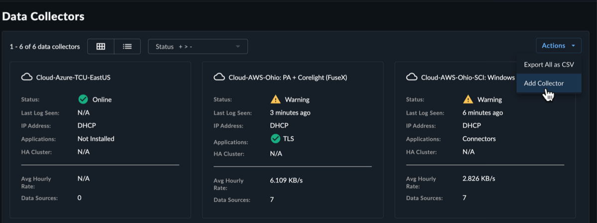
Add New Collector -
Select On-Premises as the collector type and then select Next.
-
Complete the following fields:
- Name of Collector — A nickname for the collector
- Description — (Optional) A description of the collector, such as its geographical location or the property name where it resides
-
Host Proxy — (Optional) Add an HTTP proxy address, using one of the following formats:
[http\[s]://\[user:pass@]hostname\[:port]|http://<hostname>[:port]]
-
From the HA Cluster drop-down menu, choose Yes.
-
For HA cluster with static IP address configuration, select Static, choose Configure, and follow the steps in the following Static section. For HA cluster with DHCP configuration, select DHCP and follow the steps in the following DHCP section.
Static
For static IP configuration, you must configure three nodes; for each node, fill in the following:
- Hostname — The hostname of the collector
- NTP Servers — (Optional) Specify your own NTP server Domain Name or IP address using the following format:
pool.ntp.orgorxxx.xxx.xxx.xxx - IP Address — The IP Address of the node
- Subnet Mask — The netmask of the node
- Default Gateway — The default gateway for the node
- Preferred and Alternate DNS Server — The DNS servers for the node
When all required fields for all nodes are complete, select Create Nodes and proceed to Step 7.

Add Static HA Collector Dhcp
For DHCP configuration, fill in the following:
- NTP Servers — (Optional) Specify your own NTP server Domain Name or IP address using the following format:
pool.ntp.orgorxxx.xxx.xxx.xxx - Hostname — The hostname of the collector
- IP Range — The CIDR block that specifies the range of addresses the collector nodes are allocated from. Enter one or more CIDR blocks separated by commas. If the exact IP addresses are known, then the IP addresses can be entered instead of CIDR blocks. CIDR blocks and IP addresses can be intermixed as necessary by separating multiple entries with commas. This range is used to adjust collector settings so that node-to-node communication works. Examples:
- If the DHCP address range is
192.168.22.0 - 192.168.22.255, then the CIDR block should be:192.168.22.0/24. - If the nodes could be in either of two ranges like
192.168.22.0 - 192.168.22.255or192.168.15.0 - 192.168.15.255, then you can specify both CIDR blocks separated by a comma:192.168.22.0/24,192.168.15.0/24 - If exact IP addresses are known, then you can specify those as well:
192.168.22.15,192.168.22.16,192.168.22.17
- If the DHCP address range is
When all required fields complete, select Create Collector and proceed to Step 7.

Add DHCP HA Collector Note
Default and custom NTP settings are only used during the bootstrap process on startup. Once connectivity is established, the Data Collector synchronizes time via the XDR backend connection. The NTP server value will be reflected as
ntp.collectorin the Admiral console once the connection is established. -
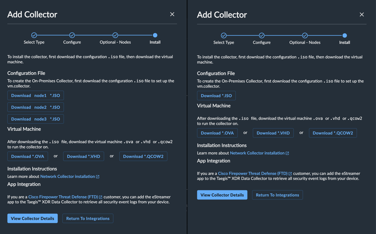
The Install Collector modal displays the following files available for download:
- One or more
.isothat contain the configuration files for your collector; one.isofor DHCP configurations used for each host, and three for static configurations, one for each host. - An
.ovathat is the virtual machine that the collector runs in. - A
.vhd, which is a .zip collection (downloaded filename is:ctpx-collector.zip) of Microsoft HyperV disk images. This is an alternative to the.ovafile. - A
.qcow2, the virtual disk preferred for Nutanix collectors.
- One or more
Save these files; you’ll use them during the installation process described below.
Installation🔗
The On-Premises Data Collector is a virtual machine appliance that must be installed in your hypervisor environment in order to collect data and transmit it to the XDR Infrastructure. It can be preconfigured and downloaded in XDR from Integrations > Data Collectors and installed in vsphere, hyperv, or nutanix environments. Once the appropriate information is provided, the collector is customized, built, and configured to DHCP or static IP addressing depending on your selection.
Once complete, an .iso cdrom image containing your client certificate/credentials and disk image in the form of .ova (vsphere) or .vhdx (hyper-v) is available for download from XDR. You are required to attach the .iso (cdrom image) to the collector VM on boot.
- For Static HA Collectors, the download consists of three
.isofiles, one per node, to download instead of one. There is one.ovaor.vhdfile to download and three.isofiles. - For DHCP HA Collectors, there is only one
.isofile to download, which is used for each node.
Once booted, the three-node appliance registers with XDR and the status of the connection displays in the XDR Console.
Note
Recommended virtual environment versions for the XDR On-Premises Data Collector are vSphere ESXi 6.7 or later or Hyper-V 8.0 in Windows Server 2016 or later.
Data Collection and Network Access Requirements🔗
The following is a reference architecture for data collection and provides an overview of the collector’s network access requirements.
Regions
Some configuration specifics of XDR depend on the region you are deployed in (US1, US2, US3, EU1, EU2).
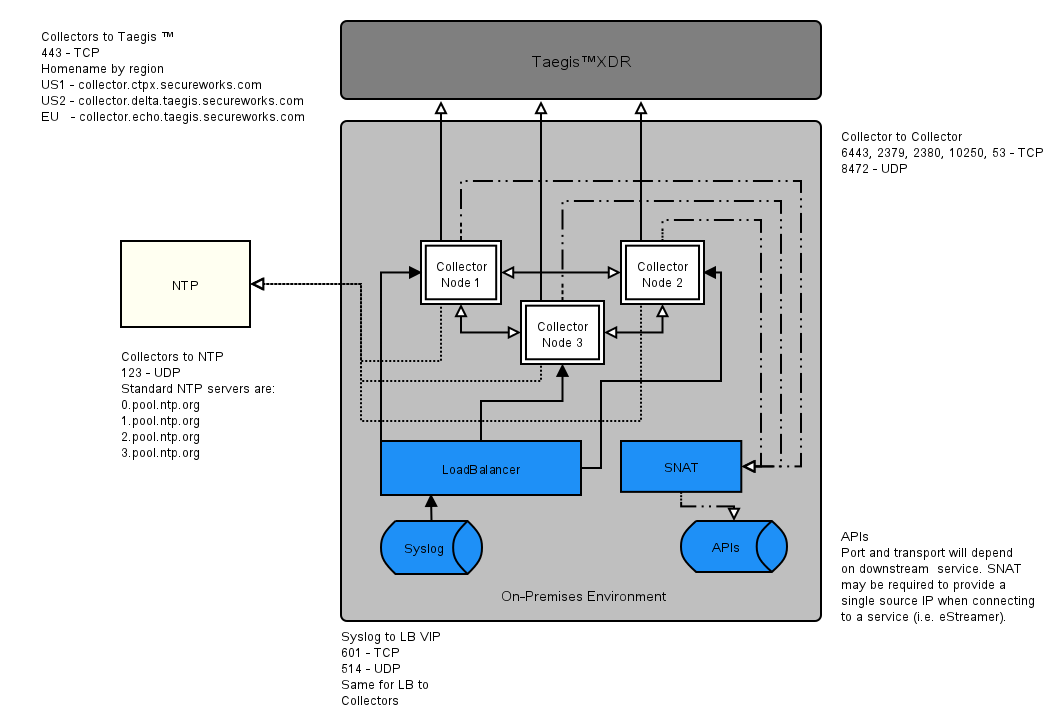
The collector acts by default as a Syslog forwarder and collects security log data. All logs that are sent to the collector are collected and transmitted using rapid batching to the XDR infrastructure. The collector listens and transmits data on the following ports, and you must allow access from inside your organization to outside on the following hostname and ports.
When configuring an HA Collector for syslog, a load balancer must be configured to provide a Virtual IP for all incoming syslog traffic. Behind the load balancer are three collector nodes. Each collector node accepts syslog traffic. The load balancer forwards the traffic from its VIP to the three downstream nodes. It accepts UDP traffic on port 514 and TCP traffic on Port 601 and forwards it to the same ports on the three collector nodes.
Note
All Syslog data is forwarded to XDR by way of a secure mTLS connection using TLS 1.3.
Taegis™ XDR Collectors forward Syslog data in batches. The frequency is optimized according to batch size and time since last forward.
Hostname and port configurations are as follows:
Outbound https on Port 443 — TCP🔗
XDR API🔗
- US1—
collector.ctpx.secureworks.com - US2—
collector.delta.taegis.secureworks.com - EU1—
collector.echo.taegis.secureworks.com - US3—
collector.foxtrot.taegis.secureworks.com - EU2—
collector.golf.taegis.secureworks.com
NTP servers: 123/UDP Outbound🔗
The XDR On-Premises Data Collector uses the following standard NTP servers:
- 0.pool.ntp.org
- 1.pool.ntp.org
- 2.pool.ntp.org
- 3.pool.ntp.org
Note
Windows DC servers cannot serve as NTP servers for non-domain hosts such as the On-Premises Data Collector.
Inbound—Syslog🔗
- 514 - UDP
- 601 - TCP
Outbound Device APIs🔗
- 443 - TCP
Inter-Node Ports🔗
The following ports must be open between the collector nodes:
- 6443, 2379, 2380, 10250, 53 - TCP
- 8472 - UDP
Connectivity Requirements for Data Collectors🔗
Note
Some configuration specifics of XDR depend on the region you are deployed in (US1, US2, US3, EU1, EU2).
Any device that uses its own SSL certificate, including Cloud-based and On-Premises Data Collectors, must safelist the following destination IP addresses or domains in order to avoid conflict. If using an AWS data collector, please refer to the AWS table.
For Most Data Collectors🔗
| Source | Destination | Port/Protocol | Notes |
|---|---|---|---|
| Data Collector IP or hostname | US1collector.ctpx.secureworks.com18.217.45.178/32 3.16.4.173/32 18.224.219.97/32 13.59.146.90/32 3.16.16.254/32 18.223.74.238/32 US2collector.delta.taegis.secureworks.com52.14.113.127/32 3.141.73.137/32 3.136.78.106/32 US3collector.foxtrot.taegis.secureworks.com44.229.101.49 35.166.77.47 34.214.135.78 EU1collector.echo.taegis.secureworks.com18.158.143.139/32 35.159.14.37/32 52.59.37.234/32 EU2collector.golf.taegis.secureworks.com54.217.251.111/32 54.194.78.20/32 52.50.215.147/32 |
TCP/443 | Safelisting device access to XDR |
| Data Collector IP or hostname | NTP severs IP/Hostnames provided during provisioning | UDP/123 | Safelisting device access to NTP servers This rule is only necessary when custom NTP servers are provided during provisioning. |
| Data Collector IP or hostname | 0.pool.ntp.org 1.pool.ntp.org 2.pool.ntp.org 3.pool.ntp.org |
UDP/123 | Safelisting device access to default NTP server. This rule is only necessary when custom NTP servers are not provided during provisioning. |
| Data Collector IP or hostname | DNS server IPs provided during provisioning | UDP/53 TCP/53 |
Safelisting device access to DNS servers |
Note
If using local NTP, the access must be safelisted both to and from the data collector on those networks.
For AWS Data Collectors🔗
| Source | Destination | Port/Protocol | Notes |
|---|---|---|---|
| AWS Data Collector IP or hostname | US1collector.ctpx.secureworks.com18.217.45.178/32 3.16.4.173/32 18.224.219.97/32 13.59.146.90/32 3.16.16.254/32 18.223.74.238/32 US2collector.delta.taegis.secureworks.com52.14.113.127/32 3.141.73.137/32 3.136.78.106/32 US3collector.foxtrot.taegis.secureworks.com44.229.101.49 35.166.77.47 34.214.135.78 EU1collector.echo.taegis.secureworks.com18.158.143.139/32 35.159.14.37/32 52.59.37.234/32 EU2collector.golf.taegis.secureworks.com54.217.251.111/32 54.194.78.20/32 52.50.215.147/32 |
TCP/443 | Safelisting device access to Taegis XDR via hostname |
| AWS Data Collector IP or hostname | NTP severs IP/Hostnames provided during provisioning | UDP/123 | Safelisting device access to NTP servers This rule is only necessary when custom NTP servers are provided during provisioning. |
| AWS Data Collector IP or hostname | 169.254.169.123 | UDP/123 | Safelisting device access to default NTP server. This rule is only necessary when custom NTP servers are not provided during provisioning. |
| AWS Data Collector IP or hostname | DNS server IPs provided during provisioning | UDP/53 TCP/53 |
Safelisting device access to DNS servers |
Proxy Support🔗
Cloud-based and On-Premises Data Collectors attempt to discover local proxy settings on the host if they are unable to connect directly to the internet.
Cloud-based and On-Premises Data Collectors also support a hard-coded proxy. If you need to create a data collector that contains a hard-coded proxy, please submit a support request with the following required information:
- Proxy IP
- Proxy Port
If the proxy is configured but is unavailable or not reachable, the data collector will fall back to a direct connection.
Note
Cloud-based and On-Premises Data Collectors do not support hard-coded authenticated proxies at this time. A proxy with man in the middle (MITM) capability needs to safelist the above network connections.
Spool Log Cache🔗
A 200GB spool log holds data when the forwarding connection to XDR is slowed or temporarily unavailable.
Virtual Machine Requirements🔗
Important
Data Collectors only support x86-64-v2 micro-architecture level. The x86-64-v2 micro-architecture defines specific features on top of the x86-64 baseline architecture that is found on most modern CPUs that have a feature level matching the 2008 Intel Nehalem architecture. These features provide compile-time optimizations for increased speed and performance. Virtual Machine configurations that do not meet this requirement will fail to boot.
Virtual Machine Requirements:
- 4 vCPUs at 2Ghz or greater
- 20GB root disk
- 200GB secondary data disk
- 8GB of Memory
Configuration🔗
XDR steps you through collector configuration and provides an .iso with credentials and configuration for the collector and an .ova virtual image that you then deploy in your environment.
Set Up On-Premises Data Collector with vSphere🔗
The following steps guide you through installation of the XDR On-Premises Data Collector. It is assumed you have the preconfigured .iso and .ova files on hand. If you still need those, navigate to Integrations > Data Collectors in XDR or contact your XDR representative.
For HA Collectors, you need three VMs. Complete the following Steps 1-14 three times. DHCP collectors have just one .iso file that are used for each VM. Each collector with a static IP address has a different .iso file.
Install the On-Premises Data Collector on VMware vSphere🔗
-
Make sure you have the
.isoand.ovafiles you need to run the collector appliance. You can preconfigure and download those in XDR from Integrations > Data Collectors. -
Connect to your vSphere Web Console.
-
Navigate to Virtual Machines and select Create / Register VM.
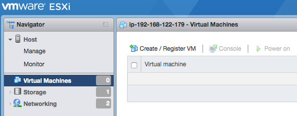
Create or Register a VM -
From Select Creation Type, select Deploy a virtual machine from an OVF or OVA file.
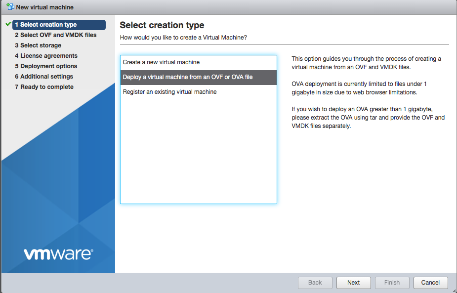
Select Creation Type -
Give your new VM a name such as
taegis-xdr-collectorand then select the.ovafile you downloaded from XDR (see Step 1 above).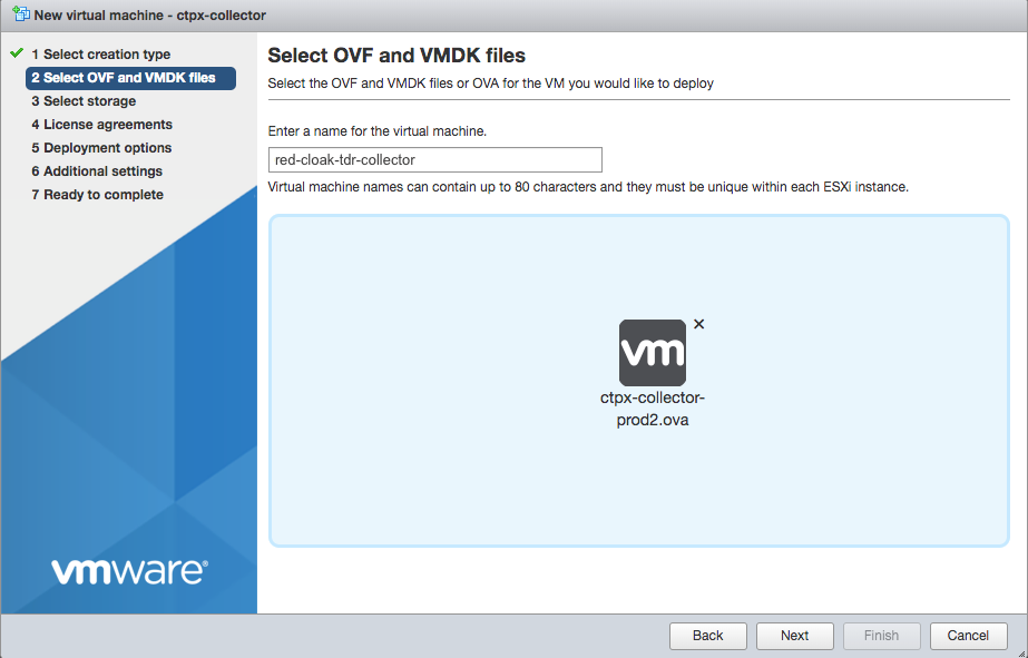
Select XDR .ova File -
Select the appropriate datastore where you want to store the VM’s disk images.
Important
Choose a datastore with at least 220GB of free space for the VM. 20GB is needed for the primary and 200GB for the secondary drive.
-
Choose your preferred network and disk configurations.
-
In the Deployment Options section, make sure to uncheck Power On Automatically. Review the configuration and then select Finish.
Steps 1-8 -
Navigate to Storage and choose Datastore Browser.
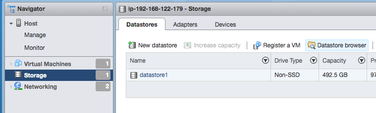
Select Datastore Browser -
Select the datastore where you want to store the XDR On-Premises Data Collector configuration
.iso(see Step 1). - Click Upload and select the configuration
.iso. -
Navigate back to Virtual Machines, and right-click the VM to bring up the context menu. Choose Edit Settings from the context menu.
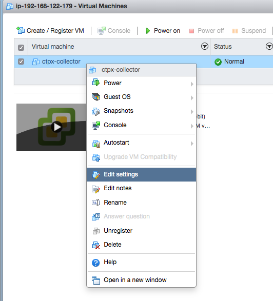
Edit Settings -
Change the CDROM device from Client Device to Datastore ISO File.
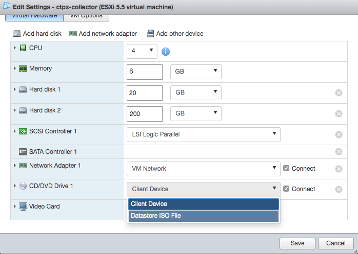
Select Datastore .iso -
The Datastore Browser opens. From there select the
.isoyou uploaded in Step 11 and click Save to finalize the changes.Note
DHCP HA Collectors have only one
.isofile. HA Collectors with static IP addresses have three. In the case of static collectors, you must use each.isoonce so that each VM gets assigned a different.isofile. In the case of DHCP collectors, use the same.isofile on every VM.Once you have completed Step 14, go back to Step 1 to create the next node. Once you have stood up the three nodes, you are done creating your VMs. After the three VMs have been configured, proceed to Step 15.
-
The VM is now ready to be powered on.
Once a VM comes online, it must stay online until all VMs have joined. This is required as the cluster does not allow new VMs to join the HA cluster if any other VM is down or unreachable. In other words, bring the first VM up, leave it running, then bring the second VM up. Then, leaving both these VMs up, bring up the third VM. Don’t turn off any of the VMs until all three have joined.
Note
When deploying an onsite collector the
.isomust be mounted at first boot to configure the XDR Collector. After the XDR Collector shows "READY" in XDR, the.isocan be dismounted.
Set Up On-Premises Data Collector with Hyper-V🔗
The following steps guide you through installation of the XDR On-Premises Data Collector using a Hyper-V environment. It is assumed you have the preconfigured .iso and .ova files on hand. If you still need those, navigate to Integrations > Data Collectors in XDR or contact your XDR representative.
Install the On-Premises Data Collector on Hyper-V🔗
-
It is assumed you have the preconfigured files on hand. If you still need those, navigate to Integrations > Data Collectors in XDR or contact your XDR representative. Unzip the
ctpx_collector.zipfile downloaded from XDR when you created your On-Premises Data Collector.Tip
Place
ctpx_collector.vhdxandctpx-collector-disk2.vhdxin the same folder with the.isofile(s) as it needs to be mounted to the CD drive on the Hyper-V machine.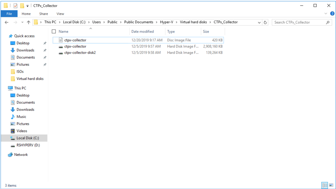
Unzip your ctpx-collector download -
Open the Hyper-V Manager and select New, then select Virtual Machine... from the context popup in the upper right pane.
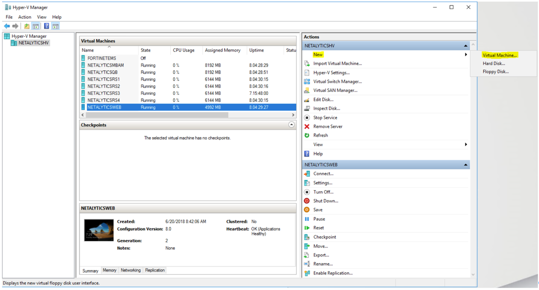
Create a New Virtual Machine -
The New Virtual Machine Wizard displays. Select Next.
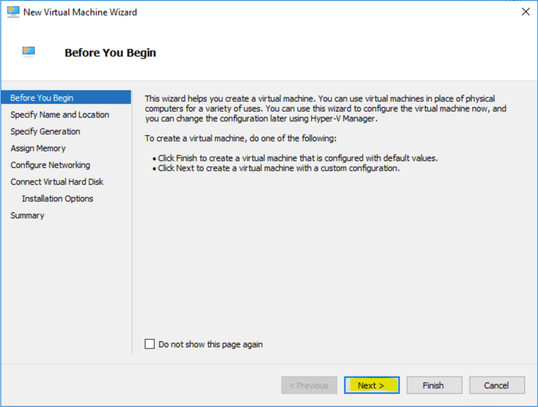
Virtual Machine Wizard The Specify Name and Location dialog displays.
-
Specify a name for the Virtual Machine then select Next.
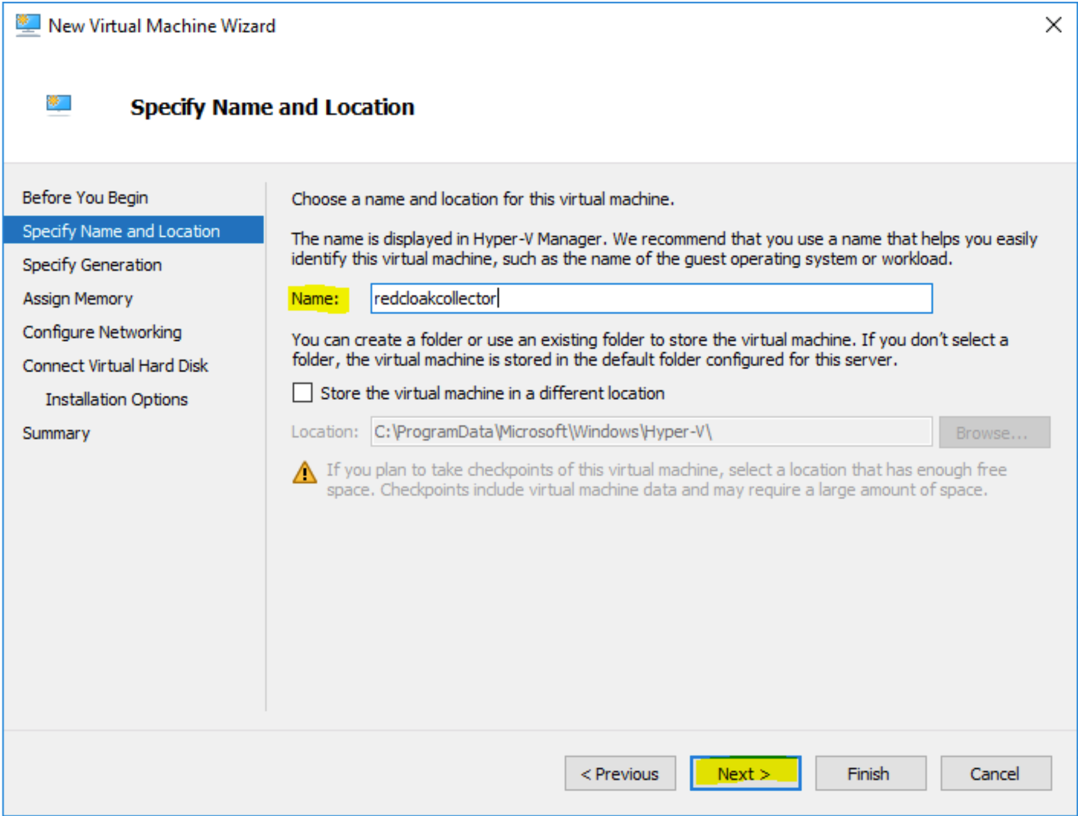
Virtual Machine Name The Specify Generation dialog displays.
-
Choose Generation 1 then select Next.
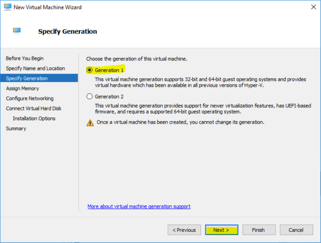
Specify Generation The Assign Memory dialog displays.
-
Assign memory (see Virtual Machine Requirements above for recommended settings) and select Next.
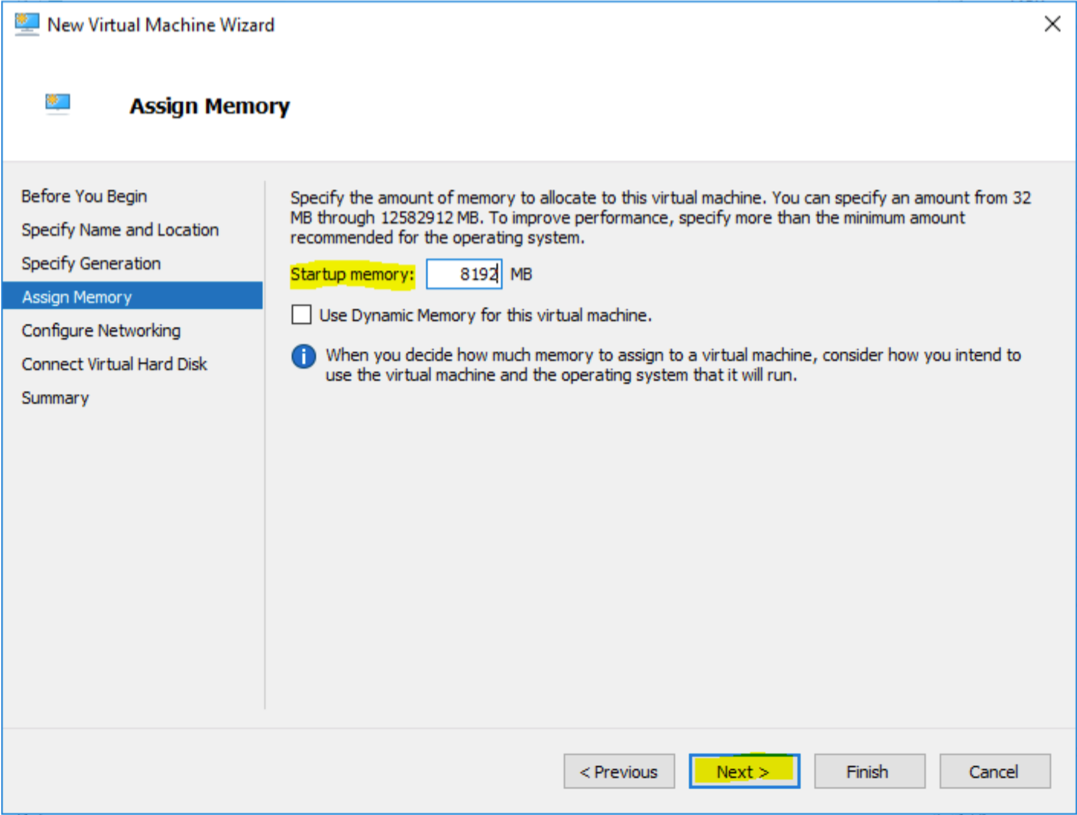
Assign Memory The Configure Networking dialog displays.
-
Choose the network adapter you are going to use with the virtual machine, then select Next.
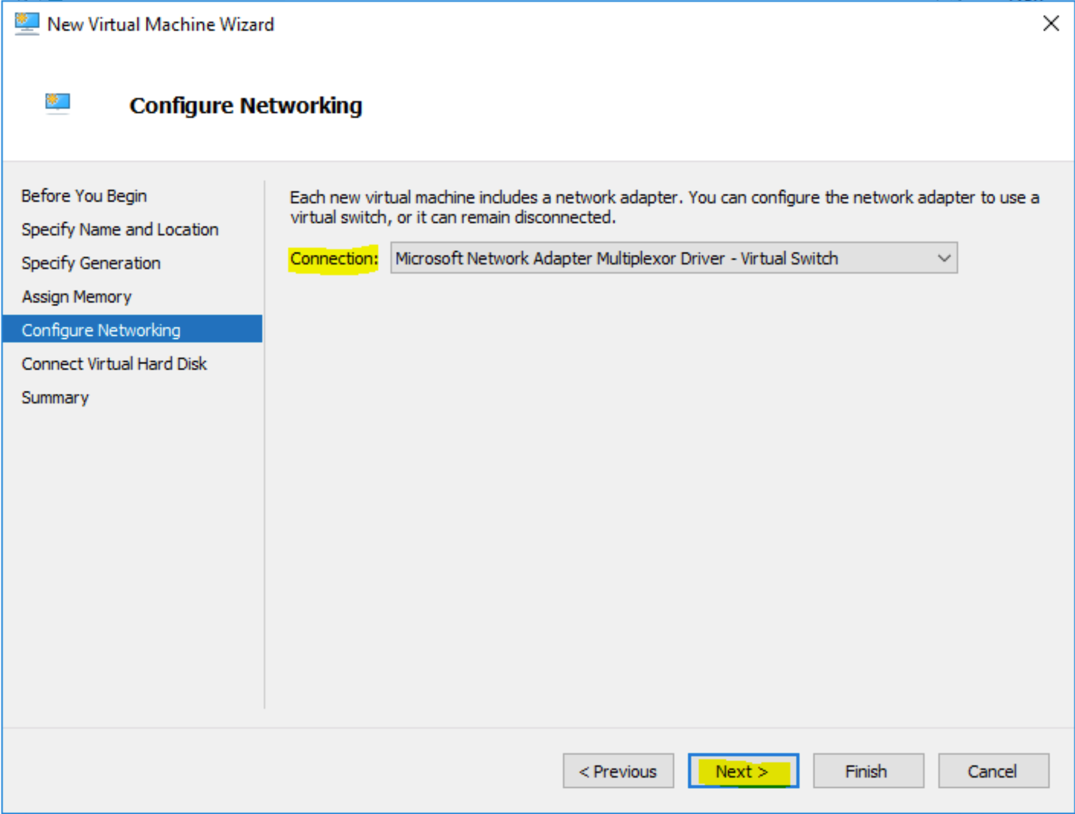
Configure Networking The Connect Virtual Hard Disk dialog displays.
-
Select Use an existing virtual hard disk and then browse to the location you chose in Step 1. Choose the
ctpx-collector.vhdxfile, then select Next.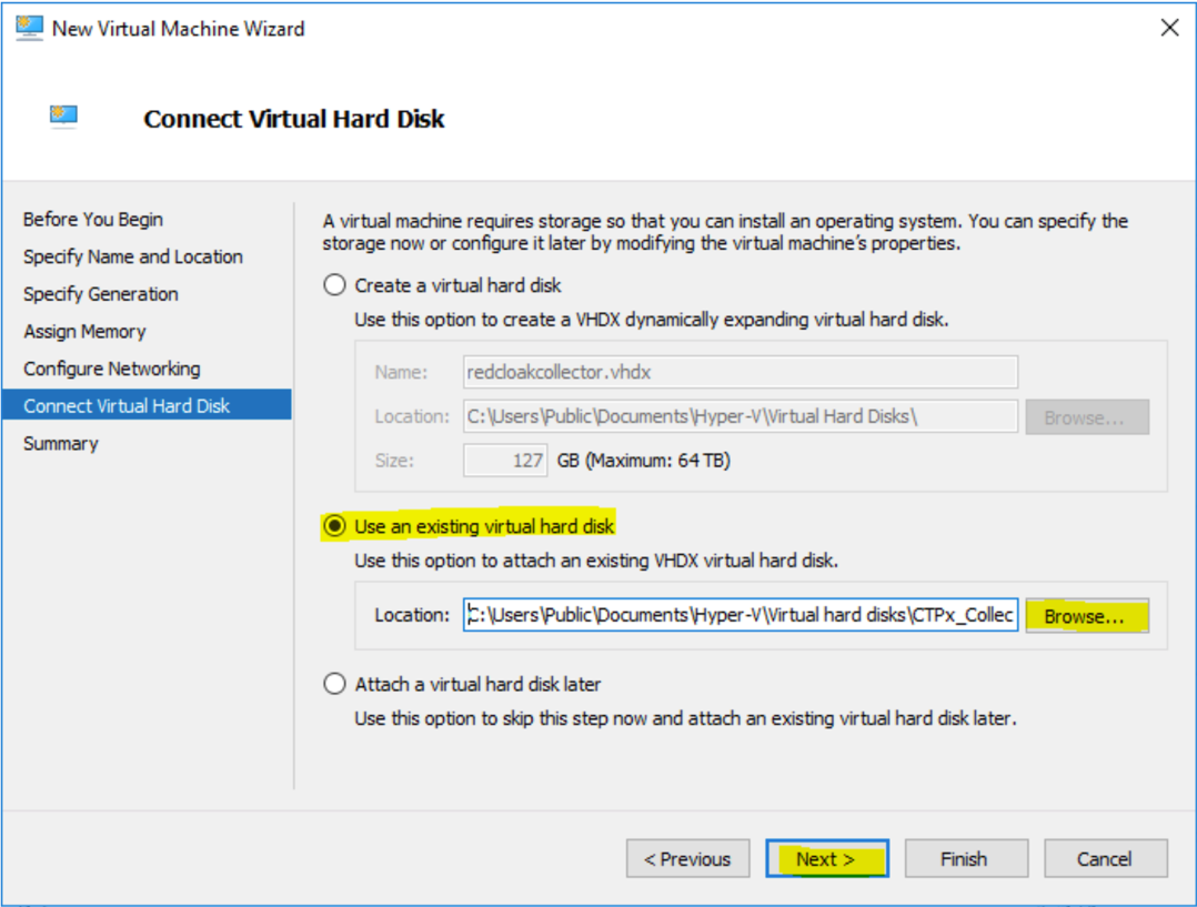
Connect Virtual Hard Disk The Completing the New Virtual Machine Wizard dialog displays.
-
Review the summary information and click Finish.
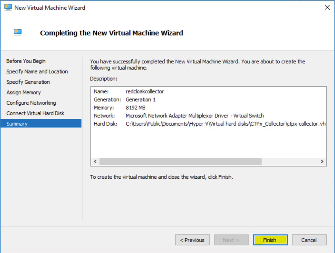
Completing the New Virtual Machine Wizard -
From the Hyper-V Manager, select the virtual machine in the Virtual Machines pane (upper center), then select Settings in the lower right pane.
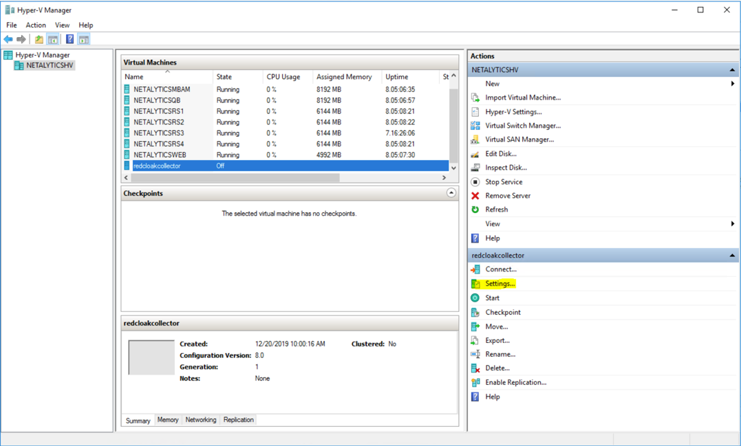
Hyper-V Manager -
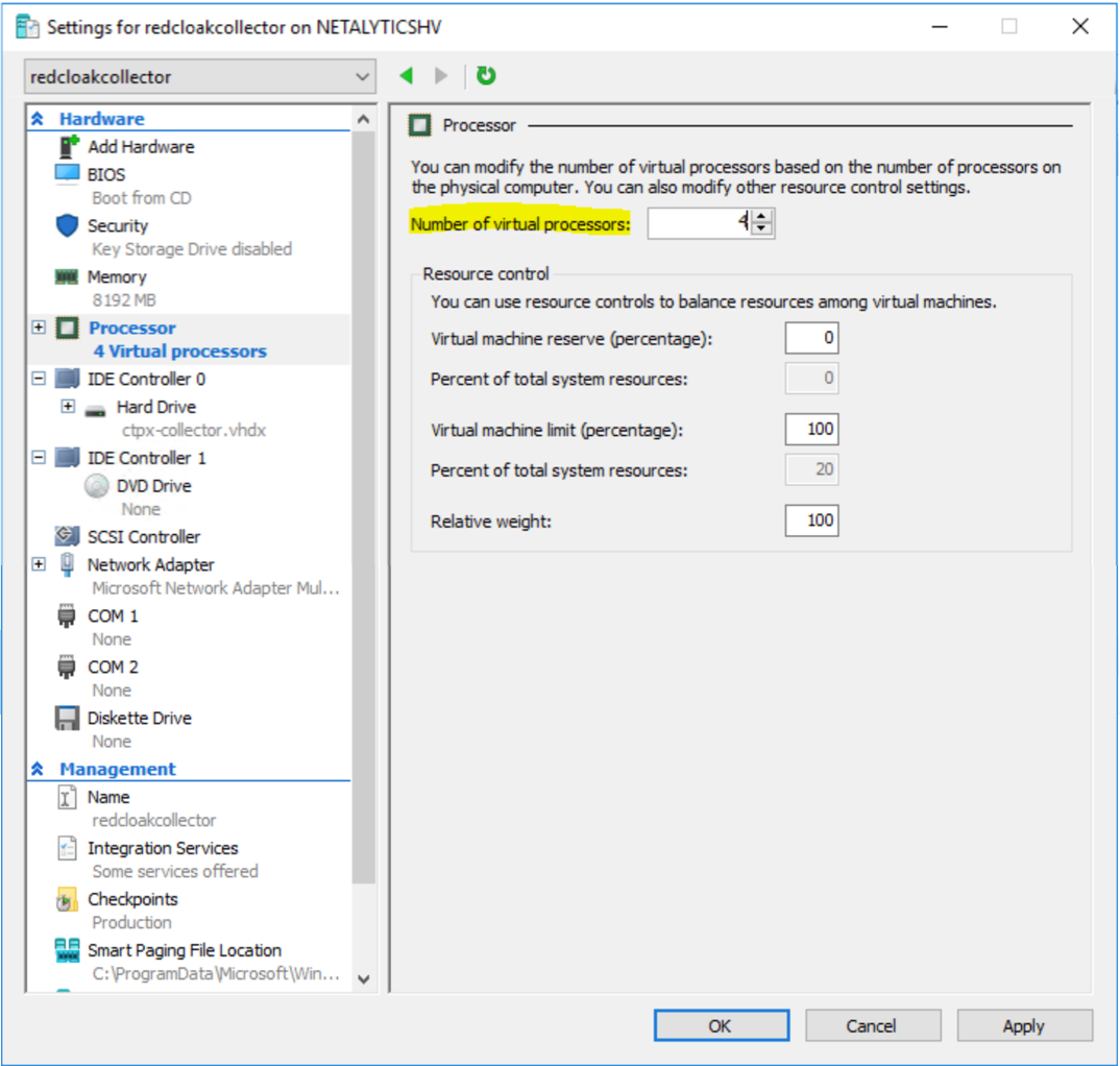
Select Processor from the Settings menu in the upper left-hand pane (see Virtual Machine Requirements above for recommended settings). Do NOT select OK or Apply at this step.
Hyper-V Processor -
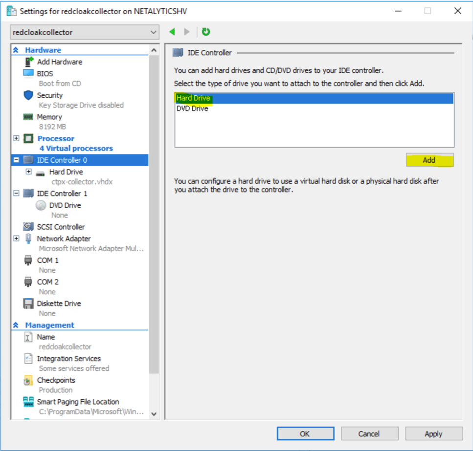
Next, open IDE Controller 0 right below Processor. The IDE Controller details display in the right-hand pane. Choose Hard Drive then select Add.
IDE Controller 0 -
Another Hard Drive appears under IDE Controller 0 in the left pane; it should be automatically selected. Select Browse..., navigate to the folder from Step 1, and choose
ctpx-collector-disk2.vhdx. Do NOT select OK or Apply at this step.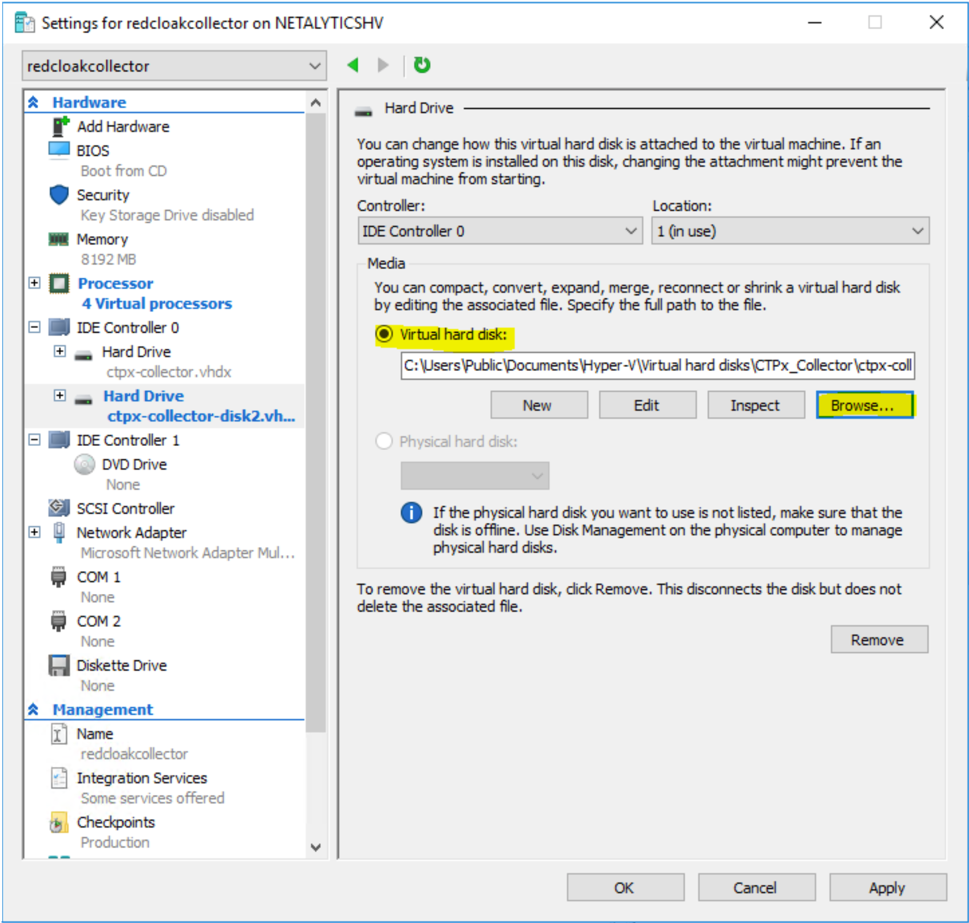
Second Hard Drive -
Click on DVD Drive under IDE Controller 1 in the upper left pane. Choose Image file:, then Browse, navigate to the folder from Step 1, and choose
ctpx-collector.iso. Do NOT select OK or Apply at this step.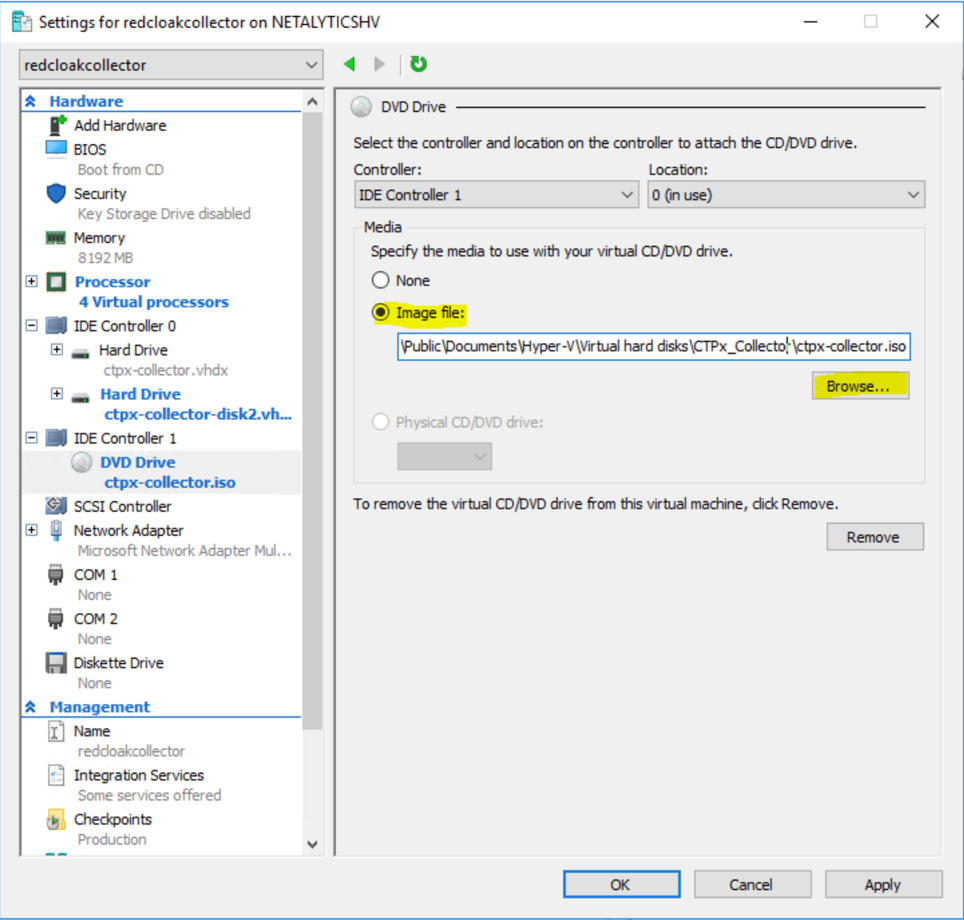
ctpx-collector.iso -
Review the Processor, IDE Controller 0, and IDE Controller 1 entries on the left pane. Verify the following selections:
Processor - 4 Virtual processors
IDE Controller 0 - Hard Drive—
ctpx-collector.vhdx- Hard Drive—ctpx-collector-disk2.vhdxIDE Controller 1: - DVD Drive—ctpx-collector.iso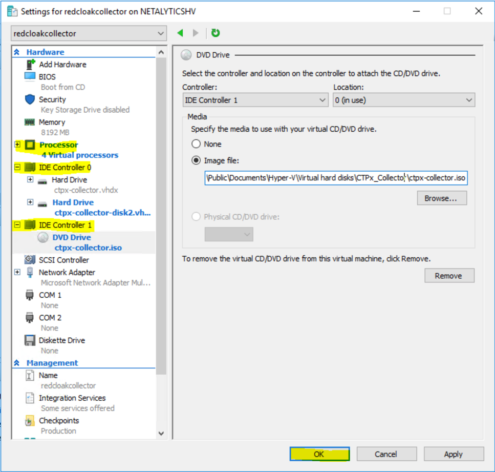
Verify Settings Once verified, select OK. The Settings menu closes.
Note
DHCP HA Collectors have only one
.isofile. HA Collectors with static IP addresses have three. In the case of static collectors, you must use each.isoonce so that each VM gets assigned a different.isofile. In the case of DHCP collectors, use the same.isofile on every VM.Once you have completed Step 15, go back to Step 1 to create the next node. Once you have stood up the three nodes, you are done creating your VMs. After the three VMs have been configured, move on to Step 16.
-
The VMs are ready to be powered on. Select the virtual machine on under Virtual Machines in the Hyper-V Manager, right-click or otherwise bring up the context menu, and select Start.
-
Once a VM comes online, it must stay online until all VMs have joined. This is required as the cluster does not allow new VMs to join the HA cluster if any other VM is down or unreachable. In other words, bring the first VM up, leave it running, then bring the second VM up. Then, leaving both these VMs up, bring up the third VM. Don’t turn off any of the VMs until all three have joined.
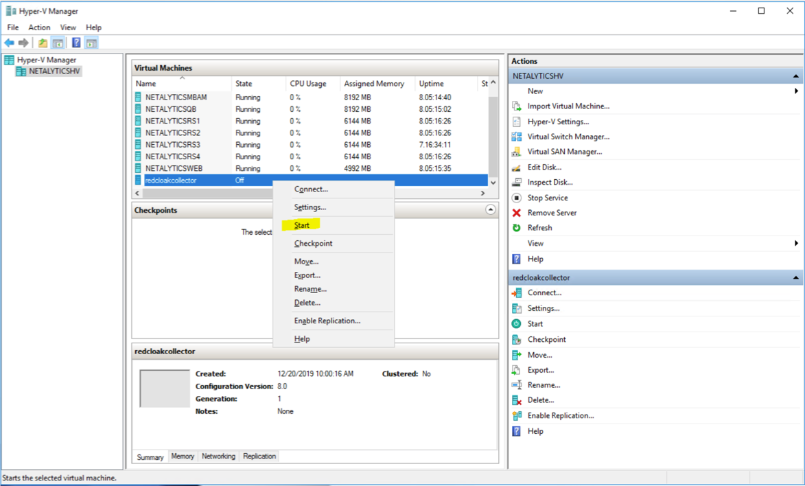
Start -
The XDR On-Premises Data Collector is now running.
Set Up On-Premises Data Collector with Nutanix🔗
The following steps guide you through installation of the XDR On-Premises Data Collector in a Nutanix environment. It is assumed you have downloaded the .qcow2 disk, preferred for Nutanix collectors, and have the ctpx-collector-nutanix.zip file on hand. If you still need those, navigate to Integrations > Data Collectors in XDR or contact your XDR representative.
Note
For HA Collectors, you need three VMs. Complete the following three times. DHCP collectors have just one .iso file that is used for each VM. Each collector with a static IP address has a different .iso file.
Install the On-Premises Data Collector on Nutanix Prism🔗
- It is assumed you have downloaded the
.qcow2disk, preferred for Nutanix collectors, and have thectpx-collector-nutanix.zipfile on hand. If you still need that, navigate to Integrations > Data Collectors in XDR or contact your XDR representative. - Unzip the
ctpx-collector-nutanix.zipfile downloaded from XDR On-Premises Data Collector when you created your On-Premises Data Collector. - Place
ctpx-collector.qcow2andctpx-collector-disk2.qcow2in the same folder with thectpx-collector.iso, as it needs to be mounted to the CD drive.
Upload Images files🔗
The disk image files and configuration ISO need to be uploaded to the Nutanix system using the Nutanix Web UI.
- Navigate to the Nutanix web console and log in.
- Select Settings from the top dropdown menu.
- Select Image Configuration from the left side Settings menu.
-
Select Upload Image and follow these steps:
- Enter a name for the image, such as
scwx-collector1. You will need this name in a later step. - Select DISK as the Image Type.
- Select Choose File to upload
ctpx-collector.qcow2and select Save.
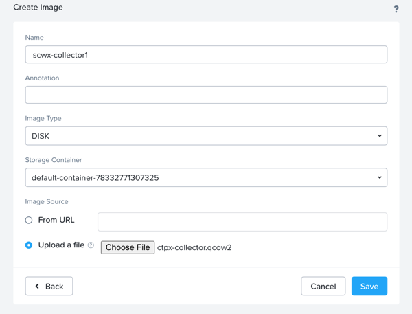
Create Image One - Enter a name for the image, such as
-
Repeat the same for
ctpx-collector-disk2.qcow2with a name such asscwx-collector2. You will need this name in a later step.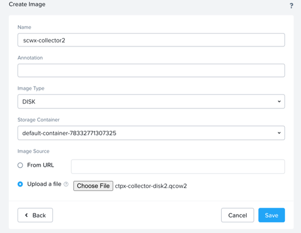
Create Image Two -
Repeat for the .iso file with a name such as
collector-isoand the Image Type as ISO.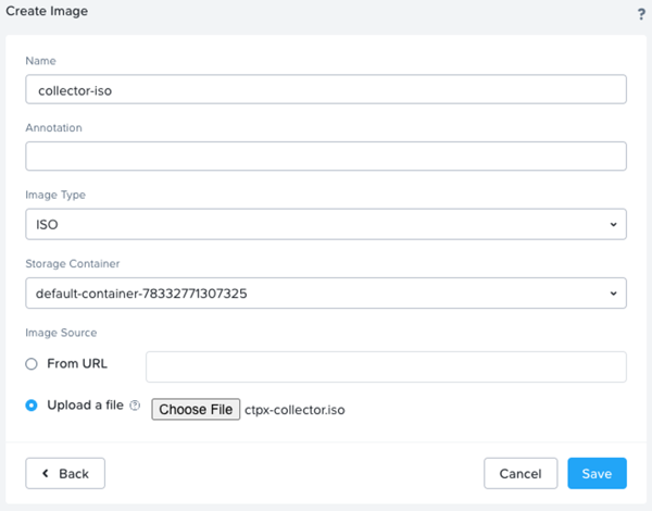
Create Image Three -
Once the upload is complete, all three files appear on the Image Configuration page.
Setting Up the VM🔗
- Select VM from the top dropdown menu of the web console.
- From the VM page, select + Create VM.
-
Enter the details of the VM:
- A Name, such as
Taegis-datacollector - Timezone = UTC
- vCPUs = 4
- Number of cores per vCPU = 1
- Memory = 8
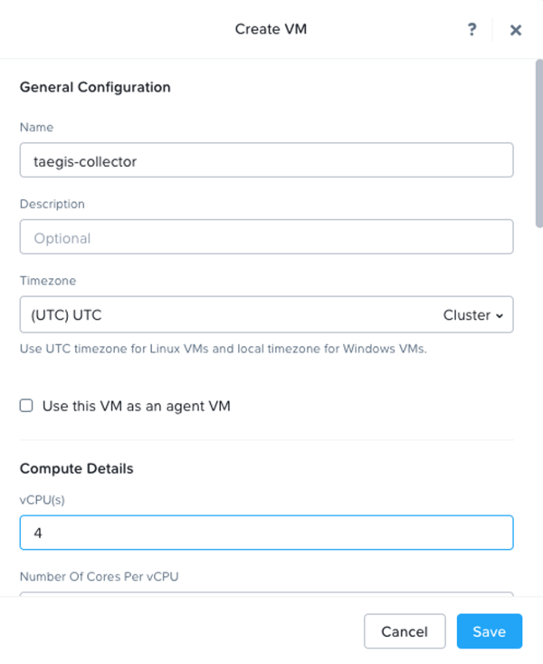
Create VM - A Name, such as
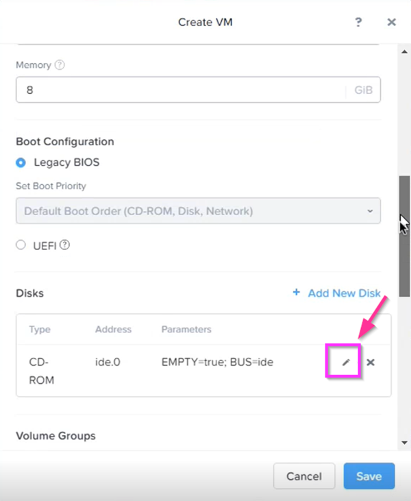
-
Scroll down to the Disks section and select the Edit pencil icon for the existing CD-ROM.
Edit Disk -
Modify the CD-ROM disk to use the .iso file as follows:
- Operation = Clone from Image Service
- Bus Type = IDE
- Image = collector-iso
- Select Update
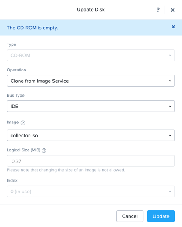
Update Disk -
Add the two additional disk images to the VM by clicking + Add New Disk.
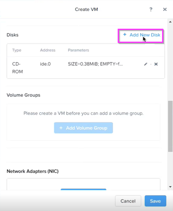
Add New Disk -
Add the first virtual disk file previously created, such as
scwx-collector1:- Type = DISK
- Operation = Clone from Image Service
- Bus Type = SCSI
- Image =
scwx-collector1or whatever you named ctpx-collector.qcow2 in the previous section - Select Add
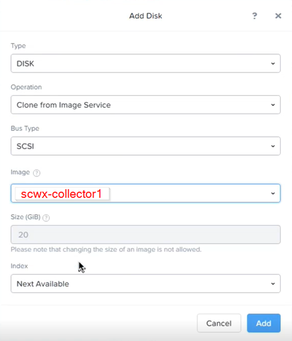
Add First Virtual Disk -
Repeat the previous step for the second disk file, such as
scwx-collector2:- Type = DISK
- Operation = Clone from Image Service
- Bus Type = SCSI
- Image =
scwx-collector2or whatever you named ctpx-collector-disk2.qcow2 in the previous section - Select Add
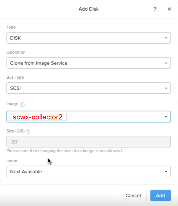
Add Second Virtual Disk -
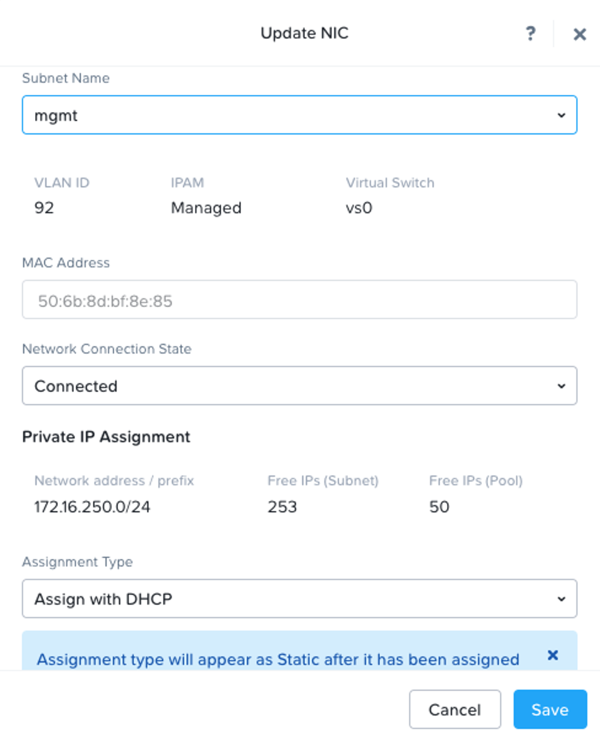
Scroll down to the Network Adapters (NIC) section, choose the network adapter you are going to use with the virtual machine. You can configure a network adapter by selecting + Add New NIC:
If Static IP is used to configure the collector, modify the Assignment Type to Assign Static IP, enter in the assigned IP address for this VM as defined during collector configuration, and select Add.
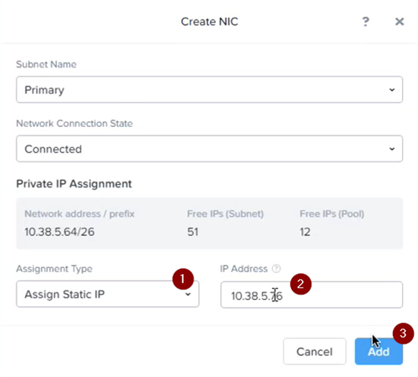
Static NIC If DHCP is used, use an appropriate subnet configured in the Nutanix portal that has DHCP enabled.
DHCP NIC -
Select Save.
Note
DHCP HA Collectors have only one .iso file. HA Collectors with static IP addresses have three. In the case of static collectors, you must use each .iso once so that each VM gets assigned a different .iso file. In the case of DHCP collectors, use the same .iso file on every VM.
-
Once you have completed Step 10, go back to Step 1 to create the next node. Once you have stood up the three nodes, you are done creating your VMs and the VM is ready to be powered on.
- Once a VM comes online, it must stay online until all VMs have joined. This is required as the cluster does not allow new VMs to join the HA cluster if any other VM is down or unreachable. In other words, bring the first VM up, leave it running, then bring the second VM up. Then, leaving both these VMs up, bring up the third VM. Don't turn off any of the VMs until all three have joined.
Maintenance or Downtime🔗
It is a requirement that any maintenance that results in downtime be performed one node at a time. After a node has been taken down for maintenance, it must be brought back online and it must have successfully rejoined the cluster before bringing the next one down. You can execute the show cluster status command in the device console to verify it has rejoined.
IP Address Changes🔗
Currently HA Collectors with statically configured IP addresses can't change their IP Address. If an IP address needs to be changed, a new HA Collector must be provisioned.
For HA Collectors with IP addresses allocated via DHCP reservation, only one node can change its IP address at a time. Also, all other nodes in the cluster must be up and running for the node to be added back to the cluster with its new IP address.
Access Troubleshooting Console🔗
The Admiral console allows you to access information about a deployed XDR Collector locally. The tools provided within Admiral assist in device setup and troubleshooting of common problems such as network connectivity.
For more information, see Admiral Console.